偙偺儁乕僕偼庯枴偺傾儅僠儏傾柍慄偐傜摼偨抦幆傪揨傔偨傕偺偱偡丅/ This page summarizes the knowledge gained from my hobby of amateur radio.丂
QTH Osaka JAPAN
Zone25-ITU45 Locator PM74tu
N-僎乕僕 乛 Model RailRoad
2022擭1寧忋弡丄庤帩偪偺RaspberryPi Zero w偵儌乕僞乕僐儞僩儘乕儔乕TA8428K偲斀幩宆僼僅僩僙儞僒乕PPR-220傪慻傒崌傢偣偰N僎乕僕傪惂屼偟傛偆偲峫偊偨丅 夞揮悢偺曌嫮傪巒傔偰丄嬋偑傝側傝偵傕揝摴柾宆傪僐儞僩儘乕儖偱偒傞傛偆偵側傝傑偟偨丅 偦偺屻丄庤帩偪偺Raspberry Pi3B偵嵎偟懼偊丄嵟屻偵HamPi偲dmonitor傪僀儞僗僩乕儖偟偨Raspberry Pi4偵揝摴柾宆偺惂屼僾儘僌儔儉傪捛壛偟傑偟偨丅 壓婰嘆儗僀傾僂僩寛掕偐傜嘋僾儘僌儔儉惉岟傑偱偺宱尡傪傑偲傔傑偟偨丅
Early January 2022, I thought of controlling the N-gauge by combining holdings the RaspberryPi Zero w with the motor controller TA8428K and the reflective photosensor PPR-220. I started to study about the rotation speed, and now I can control the model train after a fashion. After that, I replaced it with the holdings丂Raspberry Pi3B I had on hand, and finally added the model train control program to the Raspberry Pi4 on which HamPi and dmonitor were installed. Below is a summary of my experience from (1) layout decision to (4) program success.
嘆 Layout
乽仜仜仜仜仜仜仜仜乿
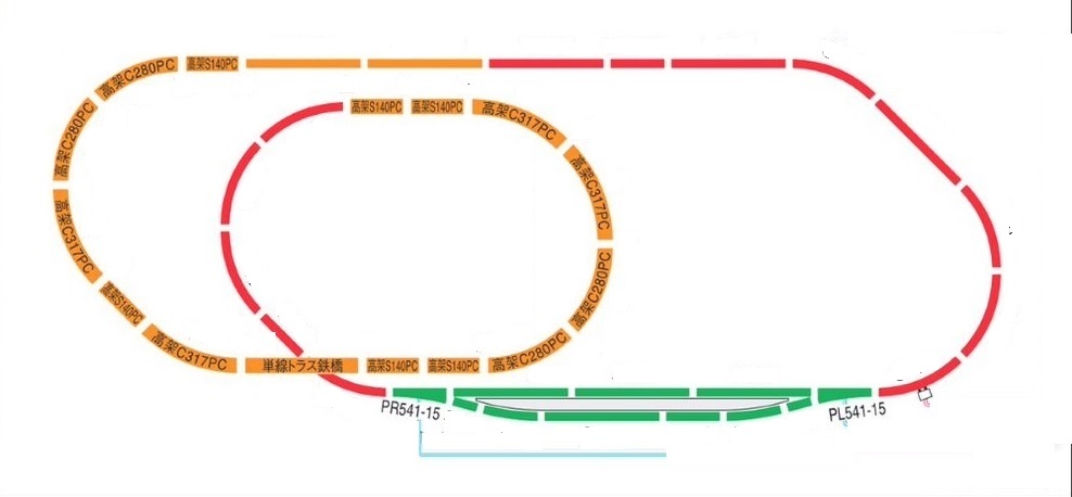
This is a layout in which rail pattern B is added to TOMIX's plan DX-PC (rail pattern A+B+C). Program the driving pattern of the vehicle in Python based on this layout.
TOMIX偺僾儔儞DX-PC(儗乕儖僷僞乕儞A+B+C)偵儗乕儖僷僞乕儞B傪捛壛偟偨儗僀傾僂僩偱偡丅偙偺儗僀傾僂僩偵婎偯偄偰幵椉偺憱峴僷僞乕儞傪Python偱僾儘僌儔儉偟傑偡丅
嘇 Pin Allocation / GPIO偺pin偲TA8428K偲PPR-220偺抂巕偺妱晅
乽仜仜仜仜仜仜仜仜乿
GPIO偺Pin
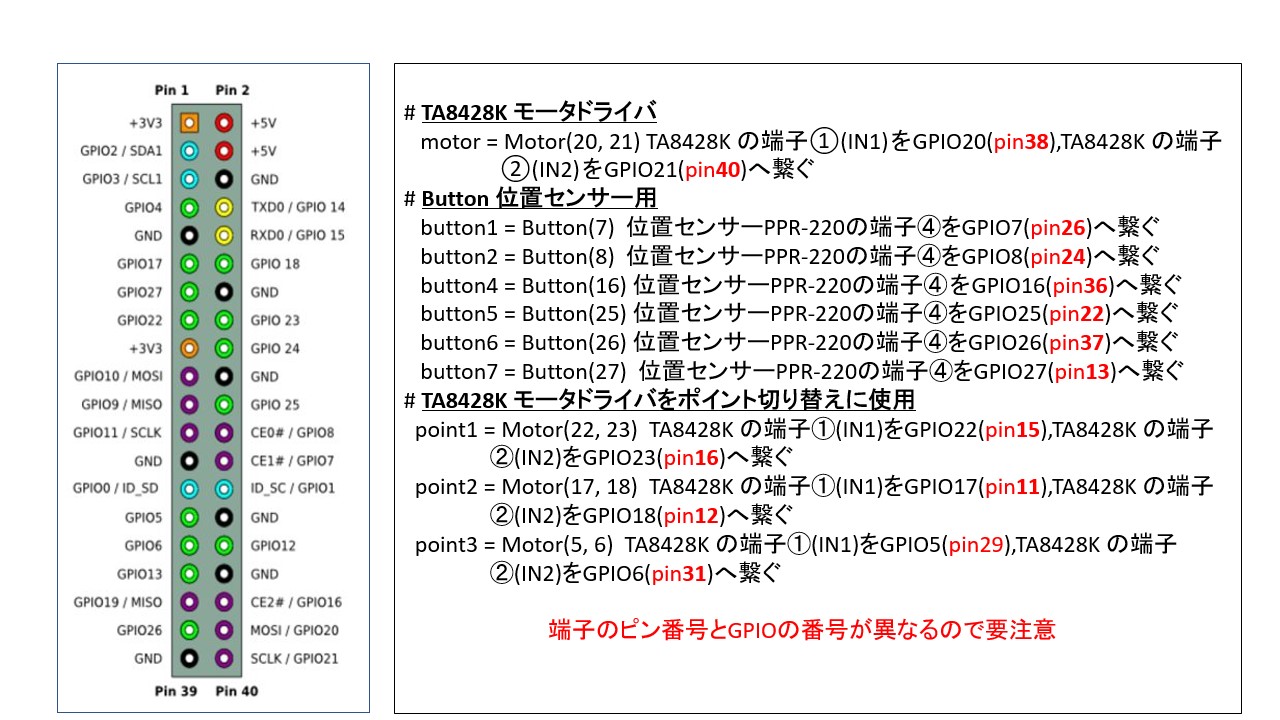
RaspberryPi4偺GPIO偺偳偺pin偐傜儌乕僞乕傗揹摦億僀儞僩傪惂屼偡傞PWM怣崋傪弌椡偟偰TA8428K偵搉偡偐丄傑偨丄偳偺pin偱斀幩宆僼僅僩僙儞僒RPR-220偺怣崋傪庴偗庢傞(擖椡偡傞)偐傪Python偺僾儘僌儔儉偺栺懇偵廬偭偰pin斣崋傪妱傝晅偗傑偡丅
T A8428K偲RPR-220偺抂巕
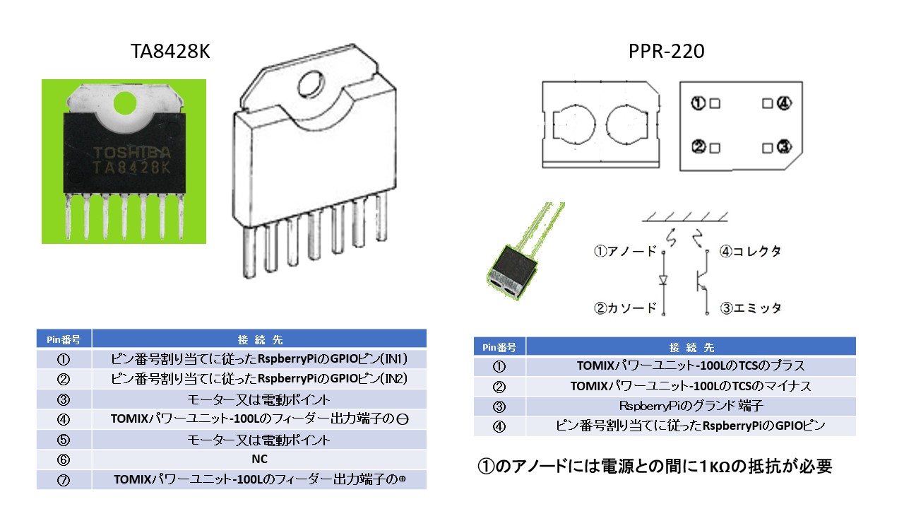
僽儗僢僪儃乕僪偵庢傝偮偗偨TA8428K偲儗僀傾僂僩忋偵愝抲偡傞斀幩宆僼僅僩僙儞僒RPR-220偺抂巕傪愭偵妱傝晅偗偨GPIO偺pin斣崋偵崌傢偣偰妱傝晅偗傑偡丅
GPIO-Pin
Which pin of the GPIO of the RaspberryPi4 outputs the PWM signal that controls the motor and "Electric Point" and passes it to the TA8428K, and which pin receives (inputs) the signal of the reflective photosensor RPR-220, assign pin numbers according to Python conventions.
Tr.A8428K and RPR-220 terminals
Assign the pins of the TA8428K attached to the breadboard and the reflective photo sensor RPR-220 installed on the layout according to the GPIO pin numbers assigned earlie.
嘊 Controller / 僐儞僩儘乕儔乕r
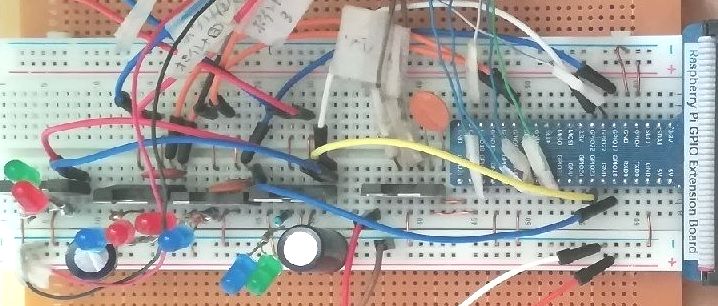
RaspberryPi4偵FREENOVE偺乽僗僞乕僞乕僉僢僩乿FNK0019偺僽儗僢僪儃乕僪傪宷偄偱丄柾宆揹幵偺懍搙惂屼梡偵TA8428K傪1屄偲TOMIX偺揹摦幃億僀儞僩愗傝懼偊梡偵TA8428K傪係屄偺崌寁俆屄偺TA8428K傪庢傝偮偗偰偄傑偡丅TA8428K偼儌乕僞乕僪儔僀僶乕梡IC偱偡偑億僀儞僩愗傝懼偊梡偵傕巊偊傑偟偨丅傑偨丄6屄偺斀幩宆僼僅僩僙儞僒RPR-220 偼揹幵偺埵抲傪専弌偟偰億僀儞僩愗傝懼偊偺怣崋偵偟偨傝丄僾儔僢僩儂乕儉傗儎乕僪偱幵椉傪掆巭偝偣傞偨傔偺怣崋偵巊偄傑偡丅
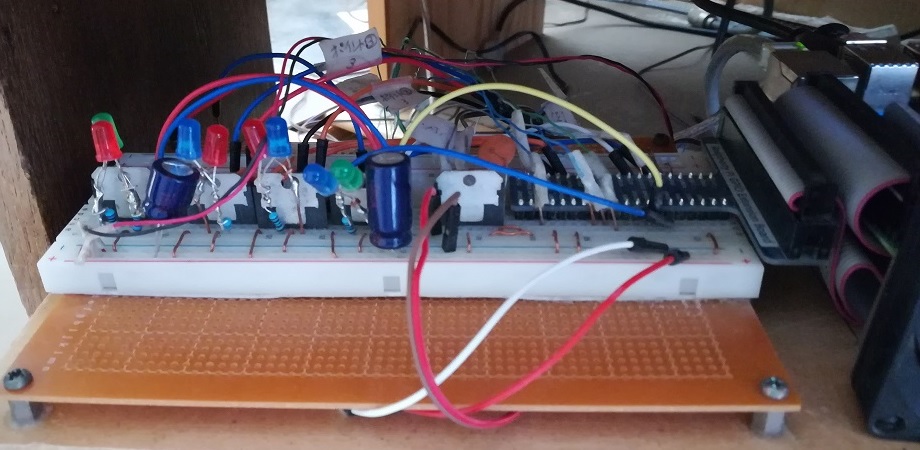
I connected the FNK0019 breadboard of FREENOVE's "starter kit" to the RaspberryPi4, and attached 1(one) TA8428K for speed control of the model train and 4(four) TA8428K for TOMIX electric point switching, for a total of 5(five) TA8428Ks. TA8428K is a motor driver IC, but it could also be used for point switching. In addition, 6 (six) reflective photo sensors RPR-220 detect the position of the train and use it as a signal for point switching, or as a signal to stop the vehicle at the platform or yard.
嘋 Programs
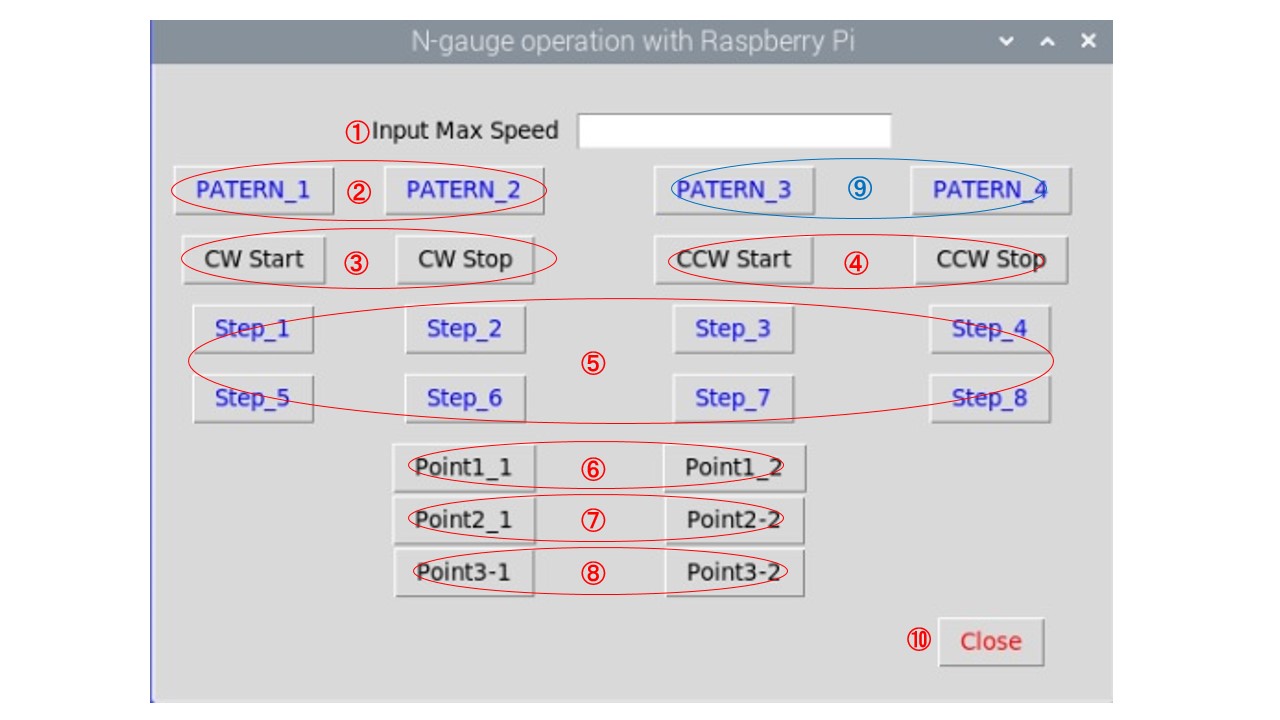
Python偼傕偲傕偲Raspberry Pi OS偺僀儊乕僕偵晅偄偰偄偨僾儘僌儔儈儞僌尵岅偱丄N僎乕僕傪惂屼偡傞偨傔偵昁梫側儔僀僽儔儕偺慻傒崬傒曽傪僀儞僞乕僱僢僩忋偺僒儞僾儖僾儘僌儔儉傪嶲峫偵偟側偑傜妛傃傑偟偨丅偦偺寢壥丄儌乕僞僪儔僀僶TA8428偲斀幩宆僼僅僩僙儞僒偺嬱摦傪埖偆GPIO梡儔僀僽儔儕偲丄幨恀偺傛偆側惂屼夋柺傪昞帵偡傞儔僀僽儔儕傪儘乕僪偡傞偩偗偱丄N僎乕僕惂屼僾儘僌儔儉偑弶傔偰姰惉偟傑偟偨丅 def暥偱8庬椶偺憱峴僷僞乕儞偺娭悢傪嶌惉偟丄僐儞僩儘乕儖夋柺忋偱憖嶌偡傞偙偲偱丄扨撈偱憖嶌偟偨傝丄偙傟傜偺娭悢傪慻傒崌傢偣偰僷僞乕儞傪曄峏偟偨傝偱偒傞傛偆偵偟偰偄傑偡丅
Python is a programming language originally attached to the image of the Raspberry Pi OS, and I learned how to incorporate the necessary libraries to control the N-gauge by referring to sample programs on the Internet. As a result, the N-gauge control program was completed for the first time just by loading the library for GPIO that handles the drive of the motor driver TA8428 and the reflective photosensor and the library that displays the control screen like the picture. I create functions for 8 types of running patterns with def statements and operate them on the control screen so that you can operate them independently or combine these functions to change the patterns.
嘋 Problems experienced before completing the program / 僾儘僌儔儉姰惉傑偱偵懱尡偟偨栤戣揰
1) 惂屼憰抲偺揹尮傪擖傟偨偲偒偵TOMIX揹摦億僀儞僩傪嶌摦偝偣傞偨傔偵巊梡偝傟偨TA8424偺惂屼僺儞1偍傛傃2偺1偮偑丄僾儘僌儔儉偝傟偨怣崋傪庴怣偣偢丄偦偺偆偪偺1偮偑LOW偱偟偨丅 TOMIX偺揹摦億僀儞僩偺僐僀儖偵12V嬤偔偺揹埑偑偐偐傝偭傁側偟偵側偭偰丄壗搙傕揹摦億僀儞僩偺僐僀儖傪從懝偟傑偟偨丅 尨場偼GPIO抂巕偲TA8424偺惂屼抂巕傪偮側偖僕儍儞僷乕慄偺愙怗晄椙偱偟偨丅 乮偼傫偩晅偗偟側偄僨儊儕僢僩丠乯 揹摦億僀儞僩偺僐僀儖偵LED傪暲楍偵愙懕偟偰摦嶌忬懺傪壜帇壔偡傞懳嶔傪峴偄傑偟偨丅
2) 斀幩宆儂僩僙儞僒乕PPR-220偼丄撥傝偺擔偲栭娫 (惏傟偨擔偱傕) 偼僾儘僌儔儉捠傝惓忢偵摦嶌偟傑偟偨偑丄惏傟偨擔偺擔拞偵岆摦嶌偟傑偟偨丅 尨場偼僙儞僒乕偑懢梲偺愒奜慄偵斀墳偟偰偄偨偨傔偱偡丅(憢偺僇乕僥儞傪暵傔傞偙偲偱栤戣偼夝寛偟傑偟偨丅)
1) TOMIX electric point when the control device was powered on does not receive a signal as programmed and one of them was LOW. There were many times that the coil of the TOMIX electric point was left with a voltage of nearly 12V, and the coil of the TOMIX electric point was burned out. Cause was poor contact of the jumper wire connecting the GPIO pin and the TA8424 control pin. (Disadvantage of not soldering?) I have countermeasured that visualize the operating state by connecting an LED in parallel with the coil of the electric point.
2) The Reflective photosensor PPR-220 worked normally on cloudy days and at night (even on sunny days) as programmed, but malfunctions during the day on sunny days. Cause was the sensor was reacting to the infrared rays of the sun (Closing the window curtains solved the problem).